Monday, July 5, 2010

What Is Radioactivity? What is Radiation?

Definition of Radioactivity and Radiation: Unstable atomic nuclei will spontaneously decompose to form nuclei with a higher stability. The decomposition process is called radioactivity. The energy and particles which are released during the decomposition process are called radiation. When unstable nuclei decompose in nature, the process is referred to as natural radioactivity. When the unstable nuclei are prepared in the laboratory, the decomposition is called induced radioactivity.

Answer: There are three major types of natural radioactivity:

  1. Alpha Radiation

Alpha radiation consists of a stream of positively charged particles, called alpha particles, which have an atomic mass of 4 and a charge of +2 (a helium nucleus). When an alpha particle is ejected from a nucleus, the mass number of the nucleus decreases by four units and the atomic number decreases by two units. For example:

23892U -> 42He + 23490Th

The helium nucleus is the alpha particle.

  1. Beta Radiation

Beta radiation is a stream of electrons, called beta particles. When a beta particle is ejected, a neutron in the nucleus is converted to a proton, so the mass number of the nucleus is unchanged, but the atomic number increases by one unit. For example:

23490 -> 0-1e + 23491Pa

The electron is the beta particle.

  1. Gamma Radiation

Gamma rays are high-energy photons with a very short wavelength (0.0005 to 0.1 nm). The emission of gamma radiation results from an energy change within the atomic nucleus. Gamma emission changes neither the atomic number nor the atomic mass. Alpha and beta emission are often accompanied by gamma emission, as an excited nucleus drops to a lower and more stable energy state.

Alpha, beta, and gamma radiation also accompany induced radioactivity. Radioactive isotopes are prepared in the lab using bombardment reactions to convert a stable nucleus into one which is radioactive. Positron (particle with the same mass as an electron, but a charge of +1 instead of -1) emission isn't observed in natural radioactivity, but it is a common mode of decay in induced radioactivity. Bombardment reactions can be used to produce very heavy elements, including many which don't occur in nature.

Introduction to Molecular Geometry

Introduction to Molecular Geometry: Molecular Geometry or molecular structure is the three-dimensional arrangement of atoms within a molecule. It is important to be able to predict and understand the molecular structure of a molecule because many of the properties of a substance are determined by its geometry.

Molecular geometry angles contain a range of question, as we have large number of results about geometry angles. Molecular geometry angles exist as person as well as with lot of other geometric figures. Most of the molecular geometry angles figures are specified by their angles, like square, rectangles, triangles etc. since of so wide presence geometric angle have lot of results in them. These lots of results make a wide range of molecular geometry angles.

The Valence Shell, Bonding Pairs, and VSEPR Model

The outermost electrons of an atom are its valence electrons. The valence electrons are the electrons that are most often involved in forming bonds and making molecules.

Pairs of electrons are shared between atoms in a molecule and hold the atoms together. These pairs are called "bonding pairs".

One way to predict the way electrons within atoms will repel each other is to apply the VSEPR (valence-shell electron-pair repulsion) model. VSEPR can be used to determine a molecule's general geometry.

Predicting Molecular Geometry

Here is a chart that describes the usual geometry for molecules based on their bonding behavior. To use this key, first draw out the Lewis structure for a molecule. Count how many electron pairs are present, including both bonding pairs and lone pairs. Treat both double and triple bonds as if they were single electron pairs. A is used to represent the central atom. B indicates atoms surrounding A. E indicates the number of lone electron pairs. Bond angles are predicted in the following order:

lone pair versus lone pair repulsion > lone pair versus bonding pair repulsion > bonding pair versus bonding pair repulsion

Molecular Geometry


Wednesday, June 16, 2010

Internal vs. External Forces

Internal vs. External Forces

There are a variety of ways to categorize all the types of forces. All the types of forces can be categorized as contact forces or as action-at-a-distance forces. Whether a force was categorized as an action-at-a-distance force was dependent upon whether or not that type of force could exist even when the objects were not physically touching. The force of gravity, electrical forces, and magnetic forces were examples of forces which could exist between two objects even when they are not physically touching. In this lesson, we will learn how to categorize forces based upon whether or not their presence is capable of changing an object's total mechanical energy. We will learn that there are certain types of forces, which when present and when involved in doing work on objects will change the total mechanical energy of the object. And there are other types of forces which can never change the total mechanical energy of an object, but rather can only transform the energy of an object from potential energy to kinetic energy (or vice versa). The two categories of forces are referred to as internal forces and external forces.

Forces can be categorized as internal forces or external forces. There are many sophisticated and worthy ways of explaining and distinguishing between internal and external forces. Many of these ways are commonly discussed at great length in physics textbooks. For our purposes, we will simply say that external forces include the applied force, normal force, tension force, friction force, and air resistance force. And for our purposes, the internal forces include the gravity forces, magnetic force, electrical force, and spring force.

Internal Forces

External Forces

Fgrav

Fspring

Fapp

Ffrict

Fair

Ftens

Fnorm


The importance of categorizing a force as being either internal or external is related to the ability of that type of force to change an object's total mechanical energy when it does work upon an object. When net work is done upon an object by an external force, the total mechanical energy (KE+PE) that object is changed. If the work is positive work, then the object will gain energy. If the work is negative work, then the object will lose energy. The gain or loss in energy can be in the form of Potential Energy, kinetic energy, or both. Under such circumstances, the work which is done will be equal to the change in mechanical energy of the object. Because external forces are capable of changing the total mechanical energy of an object, they are sometimes referred to as nonconservative forces.

When the only type of force doing net work upon an object is an internal force (for example, gravitational and spring forces), the total mechanical energy (KE+PE) that object remains constant. In such cases, the object's energy changes form. For example, as an object is "forced" from a high elevation to a lower elevation by gravity, some of the potential energy of that object is transformed into kinetic energy. Yet, the sum of the kinetic and potential energies remain constant. When the only forces doing work are internal forces, energy changes forms - from kinetic to potential (or vice versa); yet the total amount of mechanical is conserved. Because internal forces are capable of changing the form of energy without changing the total amount of mechanical energy, they are sometimes referred to as conservative forces.

Electric Field Lines

Electric Field Lines

The magnitude or strength of an electric field in the space surrounding a source charge is related directly to the quantity of charge on the source charge and inversely to the distance from the source charge. The direction of the electric field is always directed in the direction that a positive test charge would be pushed or pulled if placed in the space surrounding the source charge. Since electric field is a vector quantity, it can be represented by a vector arrow. For any given location, the arrows point in the direction of the electric field and their length is proportional to the strength of the electric field at that location. Such vector arrows are shown in the diagram below. Note that the length of the arrows are longer when closer to the source charge and shorter when further from the source charge.

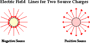
A more useful means of visually representing the vector nature of an electric field is through the use of electric field lines of force. Rather than draw countless vector arrows in the space surrounding a source charge, it is perhaps more useful to draw a pattern of several lines which extend between infinity and the source charge. These pattern of lines, sometimes referred to as electric field lines, point in the direction which a positive test charge would accelerate if placed upon the line. As such, the lines are directed away from positively charged source charges and toward negatively charged source charges. To communicate information about the direction of the field, each line must include an arrowhead which points in the appropriate direction. An electric field line pattern could include an infinite number of lines. Because drawing such large quantities of lines tends to decrease the readability of the patterns, the number of lines are usually limited. The presence of a few lines around a charge is typically sufficient to convey the nature of the electric field in the space surrounding the lines.

Charge Interactions Revisited

Charge Interactions are Forces

It is possible that we might have watched two balloons repel each other a dozen or more times and never even thought of the balloon interaction as being a force. Or perhaps you have used a plastic golf tube or other object to raise small paper bits off the lab table and never thought of Newton's laws of motion. Perhaps even now you're thinking "Why should I? That was the Newton's Laws unit and this is the Static Electricity unit." True. However, the physical world which we study does not separate itself into separate topics as we teachers and students are prone to do. Physics has an amazing way of fitting together in a seamless fashion. The information which you have forgotten about from the Newton's laws unit has a mischievous way of creeping up on you in other units. That forgetfulness (or negligence or mere ignorance) will haunt you as you try to learn new physics. The more physics which you learn (as in really learn), the more that you come to recognize that the pieces of the physics puzzle fit together to form a unified picture of the world of sight, sound, touch and feel. Here we will explore how Newton's laws of motion fit together with the interaction of charged objects.

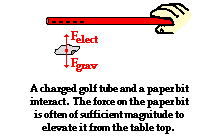
Suppose that you hold a charged plastic golf tube above a handful of paper bits at rest on the table. The presence of the charged tube is likely to polarize a few bits of paper and then begin to exert an upward pull upon them. The attraction between a charged tube and a polarized (yet neutral) paper bit is an electrical force - Felect. Like all the

forces studied in The Physics Classroom, the electrical force is a push or pull exerted upon an object as a result of an interaction with another object. The interaction is the result of electrical charges and thus it is called an electrical force.
Unlike many forces which we study, the electrical force is a non-contact force - it exists despite the fact that the interacting objects are not in physical contact with each other. The two objects can act over a separation distance and exert an influence upon each other. In this case, the plastic golf tube pulls upward upon the paper bit and a paper bit pulls downward upon the golf tube. In this case, the force is significantly small. If you were holding the golf tube, you would not likely sense the downward pull exerted upon it by the paper bit. On the other hand, the force is often large enough to either balance or even overwhelm the downward pull of gravity (Fgrav) upon the paper bit and cause it to be elevated or even accelerated off the table. Of course the actual result of the force upon the paper bit is related to Newton's laws and a free-body analysis. If at any moment, the electrical force is greater in magnitude than the gravitational force, the paper bit would be accelerated upward. And if at any moment, the electrical force is equal in magnitude to the gravitational force, the paper bit will be suspended (or levitated) in midair. The paper bit would be said to be at equilibrium.

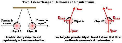
Now consider the case of the rubber balloons hanging by light threads from the ceiling. If each balloon is rubbed in the same manner (with animal fur), they each become negatively charged and exert a repulsive affect upon each other. This charge interaction results in a force upon each balloon which is directed away from the balloon with which it interacts. Once more, we can identify this repulsive affect as an electrical force. This electrical force joins two other forces which act upon the balloon - the tension force and a force of gravity. Since the balloons are at rest, the three forces must balance each other such that the net force is zero.

Both of these examples illustrate how the interaction between two charges results in a mutual force acting upon the charged objects. An electrical interaction is a force which, like any force, can be analyzed using a free-body diagram and Newton's laws. But what factors affect the magnitude of this force? Is there an equation which can be used to quantify it the same manner as was done for the force of gravity (Fgrav = m•g) and the force of friction (Ffrict = mu•Fnorm)? The answer is Yes! Coulomb's law holds the key to understanding the answer to these questions.

How Can an Insulator be Polarized?

How Can an Insulator be Polarized?

Polarization can occur within insulators, but the process occurs in a different manner than it does within a conductor. In a conducting object, electrons are induced into movement across the surface of the conductor from one side of the object to the opposite side. In an insulator, electrons merely redistribute themselves within the atom or molecules nearest the outer surface of the object. To understand the electron redistribution process, it is important to take another brief excursion into the world of atoms, molecules and chemical bonds.

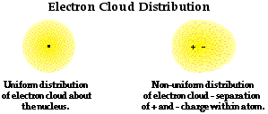
The electrons surrounding the nucleus of an atom are believed to be located in regions of space with specific shapes and sizes. The actual size and shape of these regions is determined by the high-powered mathematical equations common to Quantum Mechanics. Rather than being located a specific distance from the nucleus in a fixed orbit, the electrons are simply thought of as being located in regions often referred to as electron clouds. At any given moment, the electron is likely to be found at some location within the cloud. The electron clouds have varying density; the density of the cloud is considered to be greatest in the portion of the cloud where the electron has the greatest probability of being found at any given moment. And conversely, the electron cloud density is least in the regions where the electron is least likely to be found. In addition to having varying density, these electron clouds are also highly distortable. The presence of neighboring atoms with high electron affinity can distort the electron clouds around atoms. Rather than being located symmetrically about the positive nucleus, the cloud becomes asymmetrically shaped. As such, there is a polarization of the atom as the centers of positive and negative charge are no longer located in the same location. The atom is still a neutral atom; it has just become polarized.

The discussion becomes even more complex (and perhaps too complex for our purposes) when we consider molecules - combination of atoms bonded together. In molecules, atoms are bonded together as protons in one atom attract the electrons in the clouds of another atom. This electrostatic attraction results in a bond between the two atoms. Electrons are shared by the two atoms as they begin to overlap their electron clouds. If the atoms are of different types (for instance, one atom is Hydrogen and the other atom is Oxygen), then the electrons within the clouds of the two atoms are not equally shared by the atoms. The clouds become distorted, with the electrons having the greatest probability of being found closest to the more electron-greedy atom. The bond is said to be a polar bond. The distribution of electrons within the cloud is shifted more towards one atom than towards the other atom. This is the case for the two hydrogen-oxygen bonds in the water molecule. Electrons shared by these two atoms are drawn more towards the oxygen atom than towards the hydrogen atom. Subsequently, there is a separation of charge, with oxygen having a partially negative charge and hydrogen having a partially positive charge.

It is very common to observe this polarization within molecules. In molecules which have long chains of atoms bonded together, there are often several locations along the chain or near the ends of the chain that have polar bonds. This polarization leaves the molecule with areas which have a concentration of positive charges and other areas with a concentration of negative charges. This principle is utilized in the manufacture of certain commercial products which are used to reduce static cling. The centers of positive and negative charge within the product are drawn to excess charge residing on the clothes. There is a neutralization of the static charge buildup on the clothes, thus reducing their tendency to be attracted to each other. (Other products actually use a different principle. During manufacturing, a thin sheet is soaked in a solution containing positively charged ions. The sheet is tossed into the dryer with the clothes. Being saturated with positive charges, the sheet is capable of attracting excess electrons which are scuffed off of clothes during the drying cycle.)

Mathematics of Satellite Motion

Mathematics of Satellite Motion

The motion of objects are governed by Newton's laws. The same simple laws which govern the motion of objects on earth also extend to the heavens to govern the motion of planets, moons, and other satellites. The mathematics which describes a satellite's motion are the same mathematics presented for circular motion. In this part we will be concerned with the variety of mathematical equations which describe the motion of satellites.

Consider a satellite with mass Msat orbiting a central body with a mass of mass MCentral. The central body could be a planet, the sun or some other large mass capable of causing sufficient acceleration on a less massive nearby object. If the satellite moves in circular motion, then the net centripetal force acting upon this orbiting satellite is given by the relationship

Fnet = ( Msat • v2 ) / R

This net centripetal force is the result of the gravitational force which attracts the satellite towards the central body and can be represented as

Fgrav = ( G • Msat • MCentral ) / R2

Since Fgrav = Fnet, the above expressions for centripetal force and gravitational force can be set equal to each other. Thus,

(Msat • v2) / R = (G • Msat • MCentral ) / R2

Observe that the mass of the satellite is present on both sides of the equation; thus it can be canceled by dividing through by Msat. Then both sides of the equation can be multiplied by R, leaving the following equation.

v2 = (G • MCentral ) / R

Taking the square root of each side, leaves the following equation for the velocity of a satellite moving about a central body in circular motion

where G is 6.673 x 10⁻¹¹ N•m2/kg2, Mcentral is the mass of the central body about which the satellite orbits, and R is the radius of orbit for the satellite.

Similar reasoning can be used to determine an equation for the acceleration of our satellite that is expressed in terms of masses and radius of orbit. The acceleration value of a satellite is equal to the acceleration of gravity of the satellite at whatever location which it is orbiting. In below, the equation for the acceleration of gravity was given as

g = (G • Mcentral)/R2

Thus, the acceleration of a satellite in circular motion about some central body is given by the following equation

where G is 6.673 x 10⁻¹¹ N•m2/kg2, Mcentral is the mass of the central body about which the satellite orbits, and R is the average radius of orbit for the satellite.

The final equation which is useful in describing the motion of satellites is Newton's form of Kepler's third law. Since the logic behind the development of the equation has been presented elsewhere, only the equation will be presented here. The period of a satellite (T) and the mean distance from the central body (R) are related by the following equation:

where T is the period of the satellite, R is the average radius of orbit for the satellite (distance from center of central planet), and G is 6.673 x 10⁻¹¹ N•m2/kg2.

There is an important concept evident in all three of these equations - the period, speed and the acceleration of an orbiting satellite are not dependent upon the mass of the satellite.

None of these three equations has the variable Msatellite in them. The period, speed and acceleration of a satellite is only dependent upon the radius of orbit and the mass of the central body which the satellite is orbiting. Just as in the case of the motion of projectiles on earth, the mass of the projectile has no affect upon the acceleration towards the earth and the speed at any instant. When air resistance is negligible and only gravity is present, the mass of the moving object becomes a non-factor. Such is the case of orbiting satellites.

The Meaning of Force

The Meaning of Force

A force is a push or pull upon an object resulting from the object's interaction with another object. Whenever there is an interaction between two objects, there is a force upon each of the objects. When the interaction ceases, the two objects no longer experience the force. Forces only exist as a result of an interaction.

For simplicity sake, all forces (interactions) between objects can be placed into two broad categories:

  • contact forces, and
  • forces resulting from action-at-a-distance

Contact forces are those types of forces which result when the two interacting objects are perceived to be physically contacting each other. Examples of contact forces include frictional forces, tensional forces, normal forces, air resistance forces, and applied forces.

Action-at-a-distance forces are those types of forces which result even when the two interacting objects are not in physical contact with each other, yet are able to exert a push or pull despite their physical separation. Examples of action-at-a-distance forces include gravitational forces. For example, the sun and planets exert a gravitation pull each other despite their large spatial separation. Even when your feet leave the earth and you are no longer in physical contact with the earth, there is a gravitational pull between you and the Earth. Electric forces are action-at-a-distance forces. For example, the protons in the nucleus of an atom and the electrons outside the nucleus experience an electrical pull towards each other despite their small spatial separation. And magnetic forces are action-at-a-distance forces. For example, two magnets can exert a magnetic pull on each other even when separated by a distance of a few centimeters.

Examples of contact and action-at-distance forces are listed in the table below.

Contact Forces

Action-at-a-Distance Forces

Frictional Force
Gravitational Force
Tension Force
Electrical Force
Normal Force
Magnetic Force
Air Resistance Force

Applied Force

Spring Force

Force is a quantity which is measured using the standard metric unit known as the Newton. A Newton is abbreviated by a "N." To say "10.0 N" means 10.0 Newtons of force. One Newton is the amount of force required to give a 1-kg mass an acceleration of 1 m/s/s. Thus, the following unit equivalency can be stated:

A force is a vector quantity. A vector quantity is a quantity which has both magnitude and direction. To fully describe the force acting upon an object, you must describe both the magnitude (size or numerical value) and the direction. Thus, 10 Newtons is not a full description of the force acting upon an object. In contrast, 10 Newtons, downwards is a complete description of the force acting upon an object; both the magnitude (10 Newtons) and the direction (downwards) are given.

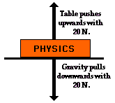
Because a force is a vector which has a direction, it is common to represent forces using diagrams in which a force is represented by an arrow.The size of the arrow is reflective of the magnitude of the force and the direction of the arrow reveals the direction which the force is acting. (Such diagrams are known as free-body diagrams). Furthermore, because forces are vectors, the affect of an individual force upon an object is often canceled by the affect of another force. For example, the affect of a 20-Newton upward force acting upon a book is canceled by the affect of a 20-Newton downward force acting upon the book. In such instances, it is said that the two individual forces balance each other; there would be no unbalanced force upon the book.

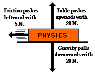
Other situations could be imagined in which two of the individual vector forces cancel each other ("balance"), yet a third individual force exists that is not balanced by another force. For example, imagine a book sliding across the rough surface of a table from left to right. The downward force of gravity and the upward force of the table supporting the book act in opposite directions and thus balance each other. However, the force of friction acts leftwards, and there is no rightward force to balance it. In this case, an unbalanced force upon the book to change its state of Motion.

Polarization

Polarization

A light wave is an electromagnetic wave which travels through the vacuum of outer space. Light waves are produced by vibrating electric charges. For our purposes, it is sufficient to merely say that an electromagnetic wave is a transverse wave which has both an electric and a magnetic component.

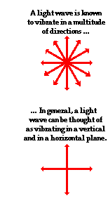
Let's suppose that we use the customary slinky to model the behavior of an electromagnetic wave. As an electromagnetic wave traveled towards you, then you would observe the vibrations of the slinky occurring in more than one plane of vibration. This is quite different than what you might notice if you were to look along a slinky and observe a slinky wave traveling towards you. Indeed, the coils of the slinky would be vibrating back and forth as the slinky approached; yet these vibrations would occur in a single plane of space. That is, the coils of the slinky might vibrate up and down or left and right. Yet regardless of their direction of vibration, they would be moving along the same linear direction as you sighted along the slinky. If a slinky wave were an electromagnetic wave, then the vibrations of the slinky would occur in multiple planes. Unlike a usual slinky wave, the electric and magnetic vibrations of an electromagnetic wave occur in numerous planes. A light wave which is vibrating in more than one plane is referred to as unpolarized light. Light emitted by the sun, by a lamp in the classroom, or by a candle flame is unpolarized light. Such light waves are created by electric charges which vibrate in a variety of directions, thus creating an electromagnetic wave which vibrates in a variety of directions. This concept of unpolarized light is rather difficult to visualize. In general, it is helpful to picture unpolarized light as a wave which has an average of half its vibrations in a horizontal plane and half of its vibrations in a vertical plane.

It is possible to transform unpolarized light into polarized light. Polarized light waves are light waves in which the vibrations occur in a single plane. The process of transforming unpolarized light into polarized light is known as polarization. There are a variety of methods of polarizing light. The four methods discussed on this page are :

Tuesday, June 15, 2010

Two Rules of Reflection for Concave Mirrors

Two Rules of Reflection for Concave Mirrors

Light always reflects according to the law of reflection, regardless of whether the reflection occurs off a flat surface or a curved surface. Using reflection laws allows one to determine the image location for an object. The image location is the location where all reflected light appears to diverge from. Thus to determine this location demands that one merely needs to know how light reflects off a mirror. The image of an object for a concave mirror was determined by tracing the path of light as it emanated from an object and reflected off a concave mirror. The image was merely that location where all reflected rays intersected. The use of the law of reflection to determine a reflected ray is not an easy task. For each incident ray, a normal line at the point of incidence on a curved surface must be drawn and then the law of reflection must be applied. A simpler method of determining a reflected ray is needed.

The simpler method relies on two rules of reflection for concave mirrors. They are:
  • Any incident ray traveling parallel to the principal axis on the way to the mirror will pass through the focal point upon reflection.
  • Any incident ray passing through the focal point on the way to the mirror will travel parallel to the principal axis upon reflection.

These two rules of reflection are illustrated in the diagram below.

These two rules will greatly simplify the task of determining the image locations for objects placed in front of concave mirrors. These two rules will be applied to determine the location, orientation, size and type of image produced by a concave mirror. As the rules are applied in the construction of ray diagrams, do not forget the fact that the law of reflection holds for each of these rays. It just so happens that when the law of reflection is applied for a ray (either traveling parallel to the principal axis or passing through F) which strikes the mirror at a location near the principal axis, the ray will reflect in close approximation with the above two rules.

Spherical Aberration

Spherical Aberration

Aberration - a departure from the expected or proper course.

Spherical mirrors have an aberration. There is an intrinsic defect with any mirror which takes on the shape of a sphere. This defect prohibits the mirror from focusing all the incident light from the same location on an object to a precise point. The defect is most noticeable for light rays striking the outer edges of the mirror. Rays which strike the outer edges of the mirror fail to focus in the same precise location as light rays which strike the inner portions of the mirror. While light rays originating at the same location on an object reflect off the mirror and focus to a point, any light rays striking the edges of the mirror fail to focus at that same point. The result is that the images of objects as seen in spherical mirrors are often blurry.
The diagram below shows six incident rays traveling parallel to the principal axis and reflecting off a concave mirror. The six corresponding reflected rays are also shown. In the diagram we can observe a departure from the expected or proper course; there is an aberration. The two incident rays which strike the outer edges (top and bottom) of the concave mirror fail to pass through the focal point. This is a departure from the expected or proper course.

This problem is not limited to light which is incident upon the mirror and traveling parallel to the principal axis. Any incident ray which strikes the outer edges of the mirror is subject to this departure from the expected or proper course. A common Physics demonstration utilizes a large demonstration mirror and a candle. The image of the candle is first projected upon a screen and focused as closely as possible. While the image is certainly discernible, it is slightly blurry. Then a cover is placed over the outer edges of the large demonstration mirror. The result is that the image suddenly becomes more clear and focused. When the problematic portion of the mirror is covered so that it can no longer focus (or mis-focus) light, the image appears more focused.
Spherical aberration is most commonly corrected by use of a mirror with a different shape. Usually, a parabolic mirror is substituted for a spherical mirror. The outer edges of a parabolic mirror have a significantly different shape than that of a spherical mirror. Parabolic mirrors create sharp, clear images which lack the blurriness which is common to those images produced by spherical mirrors.

The Law of Reflection

The Law of Reflection

Light is known to behave in a very predictable manner. If a ray of light could be observed approaching and reflecting off of a flat mirror, then the behavior of the light as it reflects would follow a predictable law known as the law of reflection. The diagram below illustrates the law of reflection.
In the diagram, the ray of light approaching the mirror is known as the incident ray (labeled I in the diagram). The ray of light which leaves the mirror is known as the reflected ray (labeled R in the diagram). At the point of incidence where the ray strikes the mirror, a line can be drawn perpendicular to the surface of the mirror. This line is known as a normal line (labeled N in the diagram). The normal line divides the angle between the incident ray and the reflected ray into two equal angles. The angle between the incident ray and the normal is known as the angle of incidence. The angle between the reflected ray and the normal is known as the angle of reflection. (These two angles are labeled with the Greek letter "theta" accompanied by a subscript; read as "theta-i" for angle of incidence and "theta-r" for angle of reflection.) The law of reflection states that when a ray of light reflects off a surface, the angle of incidence is equal to the angle of reflection.

To view an image of a pencil in a mirror, you must sight along a line at the image location. As you sight at the image, light travels to your eye along the path shown in the diagram below. The diagram shows that the light reflects off the mirror in such a manner that the angle of incidence is equal to the angle of reflection.

It just so happens that the light which travels along the line of sight to your eye follows the law of reflection. (The reason for this will be discussed later in Lesson 2). If you were to sight along a line at a different location than the image location, it would be impossible for a ray of light to come from the object, reflect off the mirror according to the law of reflection, and subsequently travel to your eye. Only when you sight at the image, does light from the object reflect off the mirror in accordance with the law of reflection and travel to your eye. This truth is depicted in the diagram below.
For example, in Diagram A above, the eye is sighting along a line at a position above the actual image location. For light from the object to reflect off the mirror and travel to the eye, the light would have to reflect in such a way that the angle of incidence is less than the angle of reflection. In Diagram B above, the eye is sighting along a line at a position below the actual image location. In this case, for light from the object to reflect off the mirror and travel to the eye, the light would have to reflect in such a way that the angle of incidence is more than the angle of reflection. Neither of these cases would follow the law of reflection. In fact, in each case, the image is not seen when sighting along the indicated line of sight. It is because of the law of reflection that an eye must sight at the image location in order to see the image of an object in a mirror.

Momentum

Momentum

Momentum is a commonly used term in sports. A team that has the momentum is on the move and is going to take some effort to stop. A team that has a lot of momentum is really on the move and is going to be hard to stop. Momentum is a physics term; it refers to the quantity of motion that an object has. A sports team which is on the move has the momentum. If an object is in motion (on the move) then it has momentum.

Momentum can be defined as "mass in motion." All objects have mass; so if an object is moving, then it has momentum - it has its mass in motion. The amount of momentum which an object has is dependent upon two variables: how much stuff is moving and how fast the stuff is moving. Momentum depends upon the variables mass and velocity. In terms of an equation, the momentum of an object is equal to the mass of the object times the velocity of the object.

Momentum = mass • velocity

In physics, the symbol for the quantity momentum is the lower case "p". Thus, the above equation can be rewritten as
p = m • v

where m is the mass and v is the velocity. The equation illustrates that momentum is directly proportional to an object's mass and directly proportional to the object's velocity.

The units for momentum would be mass units times velocity units. The standard metric unit of momentum is the kg•m/s. While the kg•m/s is the standard metric unit of momentum, there are a variety of other units which are acceptable (though not conventional) units of momentum. Examples include kg•mi/hr, kg•km/hr, and g•cm/s. In each of these examples, a mass unit is multiplied by a velocity unit to provide a momentum unit. This is consistent with the equation for momentum.

Momentum is a vector quantity. As discussed in an earlier unit, a vector quantity is a quantity which is fully described by both magnitude and direction. To fully describe the momentum of a 5-kg bowling ball moving westward at 2 m/s, you must include information about both the magnitude and the direction of the bowling ball. It is not enough to say that the ball has 10 kg•m/s of momentum; the momentum of the ball is not fully described until information about its direction is given. The direction of the momentum vector is the same as the direction of the velocity of the ball. In a previous unit, it was said that the direction of the velocity vector is the same as the direction which an object is moving. If the bowling ball is moving westward, then its momentum can be fully described by saying that it is 10 kg•m/s, westward. As a vector quantity, the momentum of an object is fully described by both magnitude and direction.

From the definition of momentum, it becomes obvious that an object has a large momentum if either its mass or its velocity is large. Both variables are of equal importance in determining the momentum of an object. Consider a Mack truck and a roller skate moving down the street at the same speed. The considerably greater mass of the Mack truck gives it a considerably greater momentum. Yet if the Mack truck were at rest, then the momentum of the least massive roller skate would be the greatest. The momentum of any object which is at rest is 0. Objects at rest do not have momentum - they do not have any "mass in motion." Both variables - mass and velocity - are important in comparing the momentum of two objects.

The momentum equation can help us to think about how a change in one of the two variables might affect the momentum of an object. Consider a 0.5-kg physics cart loaded with one 0.5-kg brick and moving with a speed of 2.0 m/s. The total mass of loaded cart is 1.0 kg and its momentum is 2.0 kg•m/s. If the cart was instead loaded with three 0.5-kg bricks, then the total mass of the loaded cart would be 2.0 kg and its momentum would be 4.0 kg•m/s. A doubling of the mass results in a doubling of the momentum.

Similarly, if the 2.0-kg cart had a velocity of 8.0 m/s (instead of 2.0 m/s), then the cart would have a momentum of 16.0 kg•m/s (instead of 4.0 kg•m/s). A quadrupling in velocity results in a quadrupling of the momentum. These two examples illustrate how the equation p = m•v serves as a "guide to thinking" and not merely a "plug-and-chug recipe for algebraic problem-solving."

Refraction and Sight

Refraction and Sight

Refraction and Sight was emphasized that we are able to see because light from an object can travel to our eyes. Every object that can be seen is seen only because light from that object travels to our eyes. As you look at Mary in class, you are able to see Mary because she is illuminated with light and that light reflects off of her and travels to your eye. In the process of viewing Mary, you are directing your sight along a line in the direction of Mary. If you wish to view the top of Mary's head, then you direct your sight along a line towards the top of her head. If you wish to view Mary's feet, then you direct your sight along a line towards Mary's feet. And if you wish to view the image of Mary in a mirror, then you must direct your sight along a line towards the location of Mary's image. This directing of our sight in a specific direction is sometimes referred to as the line of sight.

As light travels through a given medium, it travels in a straight line. However, when light passes from one medium into a second medium, the light path bends. Refraction takes place. The refraction occurs only at the boundary. Once the light has crossed the boundary between the two media, it continues to travel in a straight line. Only now, the direction of that line is different than it was in the former medium. If when sighting at an object, light from that object changes media on the way to your eye, a visual distortion is likely to occur. This visual distortion is witnessed if you look at a pencil submerged in a glass half-filled with water. As you sight through the side of the glass at the portion of the pencil located above the water's surface, light travels directly from the pencil to your eye. Since this light does not change medium, it will not refract. (Actually, there is a change of medium from air to glass and back into air. Because the glass is so thin and because the light starts and finished in air, the refraction into and out of the glass causes little deviation in the light's original direction.) As you sight at the portion of the pencil which was submerged in the water, light travels from water to air (or from water to glass to air). This light ray changes medium and subsequently undergoes refraction. As a result, the image of the pencil appears to be broken. Furthermore, the portion of the pencil which is submerged in water appears to be wider than the portion of the pencil which is not submerged. These visual distortions are explained by the refraction of light.

Longitudinal Wave

Longitudinal Wave

A longitudinal wave is a wave in which the particles of the medium are displaced in a direction parallel to the direction of energy transport. A longitudinal wave can be created in a slinky if the slinky is stretched out horizontally and the end coil is vibrated back-and-forth in a horizontal direction. If a snapshot of such a longitudinal wave could be taken so as to freeze the shape of the slinky in time, then it would look like the following diagram.
Because the coils of the slinky are vibrating longitudinally, there are regions where they become pressed together and other regions where they are spread apart. A region where the coils are pressed together in a small amount of space is known as a compression. A compression is a point on a medium through which a longitudinal wave is traveling which has the maximum density. A region where the coils are spread apart, thus maximizing the distance between coils, is known as a rarefaction. A rarefaction is a point on a medium through which a longitudinal wave is traveling which has the minimum density. Points A, C and E on the diagram above represent compressions and points B, D, and F represent rarefactions. While a transverse wave has an alternating pattern of crests and troughs, a longitudinal wave has an alternating pattern of compressions and rarefactions.

As discussed above, the wavelength of a wave is the length of one complete cycle of a wave. For a transverse wave, the wavelength is determined by measuring from crest to crest. A longitudinal wave does not have crest; so how can its wavelength be determined? The wavelength can always be determined by measuring the distance between any two corresponding points on adjacent waves. In the case of a longitudinal wave, a wavelength measurement is made by measuring the distance from a compression to the next compression or from a rarefaction to the next rarefaction. On the diagram above, the distance from point A to point C or from point B to point D would be representative of the wavelength.

Transverse Wave

Transverse Wave

A transverse wave is a wave in which the particles of the medium are displaced in a direction perpendicular to the direction of energy transport. A transverse wave can be created in a rope if the rope is stretched out horizontally and the end is vibrated back-and-forth in a vertical direction. If a snapshot of such a transverse wave could be taken so as to freeze the shape of the rope in time, then it would look like the following diagram.
The dashed line drawn through the center of the diagram represents the equilibrium or rest position of the string. This is the position that the string would assume if there were no disturbance moving through it. Once a disturbance is introduced into the string, the particles of the string begin to vibrate upwards and downwards. At any given moment in time, a particle on the medium could be above or below the rest position. Points A, E and H on the diagram represent the crests of this wave. The crest of a wave is the point on the medium which exhibits the maximum amount of positive or upwards displacement from the rest position. Points C and J on the diagram represent the troughs of this wave. The trough of a wave is the point on the medium which exhibits the maximum amount of negative or downwards displacement from the rest position.

The wave shown above can be described by a variety of properties. One such property is amplitude. The amplitude of a wave refers to the maximum amount of displacement of a particle on the medium from its rest position. In a sense, the amplitude is the distance from rest to crest. Similarly, the amplitude can be measured from the rest position to the trough position. In the diagram above, the amplitude could be measured as the distance of a line segment which is perpendicular to the rest position and extends vertically upward from the rest position to point A.
The wavelength is another property of a wave which is portrayed in the diagram above. The wavelength of a wave is simply the length of one complete wave cycle. If you were to trace your finger across the wave in the diagram above, you would notice that your finger repeats its path. A wave is a repeating pattern. It repeats itself in a periodic and regular fashion over both time and space. And the length of one such spatial repetition (known as a wave cycle) is the wavelength. The wavelength can be measured as the distance from crest to crest or from trough to trough. In fact, the wavelength of a wave can be measured as the distance from a point on a wave to the corresponding point on the next cycle of the wave. In the diagram above, the wavelength is the horizontal distance from A to E, or the horizontal distance from B to F, or the horizontal distance from D to G, or the horizontal distance from E to H. Any one of these distance measurements would suffice in determining the wavelength of this wave.

Monday, June 14, 2010

Vector Diagrams

Vector Diagrams

Vector diagrams are diagrams which depict the direction and relative magnitude of a vector quantity by a vector arrow. Vector diagrams can be used to describe the velocity of a moving object during its motion. For example, the velocity of a car moving down the road could be represented by a vector diagram.
In a vector diagram, the magnitude of a vector quantity is represented by the size of the vector arrow. If the size of the arrow in each consecutive frame of the vector diagram is the same, then the magnitude of that vector is constant. The diagrams below depict the velocity of a car during its motion. In the top diagram, the size of the velocity vector is constant, so the diagram is depicting a motion of constant velocity. In the bottom diagram, the size of the velocity vector is increasing, so the diagram is depicting a motion with increasing velocity - i.e., an acceleration.
Vector diagrams can be used to represent any vector quantity. In future studies, vector diagrams will be used to represent a variety of physical quantities such as acceleration, force, and momentum. Be familiar with the concept of using a vector arrow to represent the direction and relative size of a quantity. It will become a very important representation of an object's motion as we proceed further in our studies of the physics of motion.

Wednesday, June 9, 2010

Satellite Motion

Satellite Motion

Polar Satellite Orbit

Polar satellites travel around the Earth in an orbit that travels around the Earth over the poles. The Earth rotates on its axis as the satelitte goes around the Earth. Thus over a period of many orbits it looks down on every part of the Earth.


Geostationary Satellite Orbit


Geostationary satellites, orbit around the equator in the same direction as the Earth rotates. They are positioned at a height above the Earth such that the same time for the satellite to complete its orbit is the same as the time it takes for the Earth to rotate once about its axis, ie. 24 hours.

Using the relationship derrived earlier which showed that r3/T2=GM/4π we can calculate the height of a satellite above the Earthh necessary to achieve a geostationary orbit. (The height above the Earth's surface is the distance r minus the radius of the Earth). Since the satellite is orbiting the Earth the mass we must use in this formula is the mass of the Earth.

The time in seconds for the Earth to rotate is 24x602=86400 seconds and the mass of the Earth is 6 x 1024kg.

r3=6.67 x 10⁻¹¹ N.kg2.s-2 x 6 x 1024kg x (86400 s)2/(4x π2)

r=(9.34 x 10¹⁷)1/3

4.23 x 10⁷ m=4.23 x 10⁴ km

The radius of the Earth is 6400 km. Therefore the height of the satellite above the Earth necessary to maintain a geostationary orbit is 4.23 x 10⁴-6.4 x 10⁴ km = 3.58 x 10⁴ km

The Structure of Matter

Introduction

The Structure of Matter

The Greeks were the first to speculate that matter was discrete, in the form of particles. The word atom derives from the Greek (ατομοζ) for indivisible. Democretus, argued that matter on the large scale is composed of atoms and that different substances were composed of different atoms or combination's of atoms. Furthermore, one could substance could be converted into another simply be re-arranging the atoms. The atomic theory was roundly rejected by Aristotle, and, thus, by almost everybody else for the next two millennia.

The modern definition of an element was made in 1661 by Robert Boyle. An element is a substance that can not be broken down into simpler substances but can form compounds with other elements. There are 88 naturally occurring elements (not the much reported 92 natural elements - The elements Tc, Pm, At and Fr have no stable isotopes, and none of long half-life, so they are not naturally present.) Including man-made elements, at the time of writting (Dec, 2006) there are 117 elements. The existence of these more massive elements is fleeting with elements lasting from a few microseconds to about 30 seconds.

For the Greeks, atoms were as far as the indivisibility of matter went. However, in 1906 J. J. Thompson discovered a negatively charged particle which eventually became known as an electron. Early models the atom considered 'atom as a nice hard fellows, red or gray in color, according to taste', in which the charged particles were distributed much like the plums in a Plum pudding. However, this model of the atoms was shown to be wrong by Rutherford's experiment, in which a high energy beam of alpha particles was fired at a very thin gold foil.

rutherford's alpha particle experiment

Ruferford's alpha particle experiment.

If the plum pudding model of the atom was correct then the alpha particles would pass through the foil with little deflection. As shown in the figure.

scattering

Expected results and actual results of experiment.

Most of the alpha particle passed through the foil with very little deflection. However, about 1 in every 8000 was scattered through an angle of more than 90 degrees. To Rutherford this was incredible. “It was quite the most incredible event that has ever happened to me in my life. It was almost as incredible as if you had fired a 15-inch shell at a piece of tissue-paper and it came back and hit you.” For the alpha particles to be scattered through such large angles and even coming back on themselves, they had to encounter a massive concentration of charged particles of very small size. The back scattering of alpha particles showed that most of the mass of the atom was concentrated at the nucleus.

A Brief History of Cosmological Ideas

A Brief History of Cosmological Ideas

Aristotle

The Greek philospher Aristotle proposed that the heavens were literally composed of 55 concentric, crystalline spheres to which the celestial objects were attached and which rotated at different velocities (but the angular velocity was constant for a given sphere), with the Earth at the center.

The Ptolemaic System

The prevailing theory in Europe as Copernicus was writing was that created by Ptolemy in his Almagest, dating from about 150 A.D. The Ptolemaic system drew on many previous theories that viewed Earth as a stationary center of the universe. Stars were embedded in a large outer sphere which rotated relatively rapidly, while the planets inhabited smaller spheres as . The idea that the Earth was at the centre of the universe with everything revolving around it was one that fitted with religious beleifs. Afterall, man is the most important of God's creations and so it was proper that the Earth should be at the center of a perfect and uniform universe.


Retrograde motion of Mars

The Ptolemaic model of the universe, had the Earth at the center of the universe with the Sun and the planets travelling around in circular orbits. To accurately describe the observed data, the planets travelled in smaller orbits known as epicycles as they orbited around the Earth. This reproduced the motion of the planets as the travelled across the sky. In particular, the phenomena of retrograde motion, in which the planet sometimes appears to travel backwards or loop the loop. The illustration shows the orbit of Mars over a period of several month.